Infoportal
Dies ist eine alte Version des Dokuments!
Controller Board with Colibri Module
cb11 Board
Features
- 1 x Ethernet
- 2 x CAN
- 24 DIO
- 8 Analog Out
- For Altium files together with FPGA designs see http://wiki.ntb.ch/projects/pathos/start
Important: For this board you have to load a different FPGA configuration as for the cb20.
Existing Boards
- 1 x cb11 Prototype (EMS) 2015
cb20 Board
Features
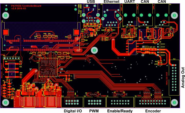
- 1 x Ethernet
- 2 x CAN
- 1 x USB Host
- 1 x Konsole, 1 x UART
- 24 DIO
- 8 Analog Out
The board has a EP4CE22F17C8 FPGA from Altera which is connected over the EIM bus to the Colibri module.
- github repository with Altium files, FPGA designs, and test application https://github.com/ntb-ch/cb20
- Hardware configuration file for EEROS https://github.com/ntb-ch/cb20/blob/master/Software/cb20test/HwConfigCb20.json
The FPGA configuration for the cb20 is made with flink. The available blocks for flink can be found on flink-Wiki.
Existing Boards
- 8 x cb20 INF (Variosystems 2016) without CAN-GND
- 2 x cb20 EMS (Variosystems 2016) without CAN-GND
- 5 x cb22 INF different power plug (Anronaut 2017)
flink Configurations
Standard FPGA Design
The FPGA is driven by a 50MHz clock. The system incorporates a Avalon ALTPLL component which multiplies this clock with 4 leading to a internal clock of 200MHz. The flink blocks which depend on this clock must set their base clock setting accordingly. This configuration defines the following subdevices:
| flink component | unique id | id | nof channels | description |
|---|---|---|---|---|
| PWM | 0x1270C001 | 0 | 8 | |
| FQD | 0x12706001 | 1 | 8 | |
| Analog Out | 0x12702001 | 2 | 8 | |
| Info Device | 0x12700001 | 3 | cb20 standard, 28.5.2020 | |
| Dig I/O | 0x12705002 | 4 | 8 | |
| Dig I/O (Enable/Ready) | 0x12705001 | 5 | 9 |
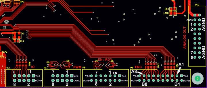
The header and pin assignment are shown below. :
Test Program
Unter https://github.com/ntb-ch/cb20 befindet sich auch ein EEROS Testprogramm für diese Konfiguration. Mit Hilfe der Skripte werden zuerst die notwendigen Repositories geholt (clone.sh). Achtung: im File config.sh.in muss für eine Crossentwicklung das notwendige Toolchainfile angegeben werden. Dann kann mit make.sh alles übersetzt werden. Anschliessend muss auf das cb20 copiert werden.
Das Testprogramm liest eine passende Hardware-Konfiguration ein.
- HwConfigCb20.json: alle Pins werden konfiguriert. Auf den analogen Ausgängen, den digitalen Ausgängen und den PWM-Ausgängen werden Werte ausgegeben. Die Encoder-Eingänge werden geloggt.
- HwConfigDb11.json: nur je vier Encoder-Eingänge, analoge Ausgänge, ready-Signale und das Enable-Signal werden konfiguriert. Zu dieser Hardware-Konfiguration gibt es ein spezielles Testprogramm (cb11Test).
FPGA Design with Watchdog and PPWA
| flink component | unique id | id | nof channels | description |
|---|---|---|---|---|
| PWM | 0x1270C001 | 0 | 4 | |
| PPWA | 0x12706001 | 1 | 2 | |
| Watchdog | 0x12710001 | 2 | 1 | |
| FQD | 0x12706001 | 3 | 8 | |
| Analog Out | 0x12702001 | 4 | 8 | |
| Info Device | 0x12700001 | 5 | cb20 with wdt, 28.5.2020 | |
| Dig I/O | 0x12705002 | 6 | 8 | |
| Dig I/O (Enable/Ready) | 0x12705001 | 7 | 9 |
FPGA Design with MPU9250
This design incorporates a SPI Connection to a MPU9250 sensor. The SPI occupies 4 pins on the PWM connector.
| flink component | unique id | id | nof channels | description |
|---|---|---|---|---|
| PWM | 0x1270C001 | 0 | 4 | |
| MPU9250 | 0x12711001 | 1 | ||
| FQD | 0x12706001 | 2 | 8 | |
| Analog Out | 0x12702001 | 3 | 8 | |
| Info Device | 0x12700001 | 4 | ||
| Dig I/O | 0x12705002 | 5 | 8 | |
| Dig I/O (Enable/Ready) | 0x12705001 | 6 | 9 |
Known Errors
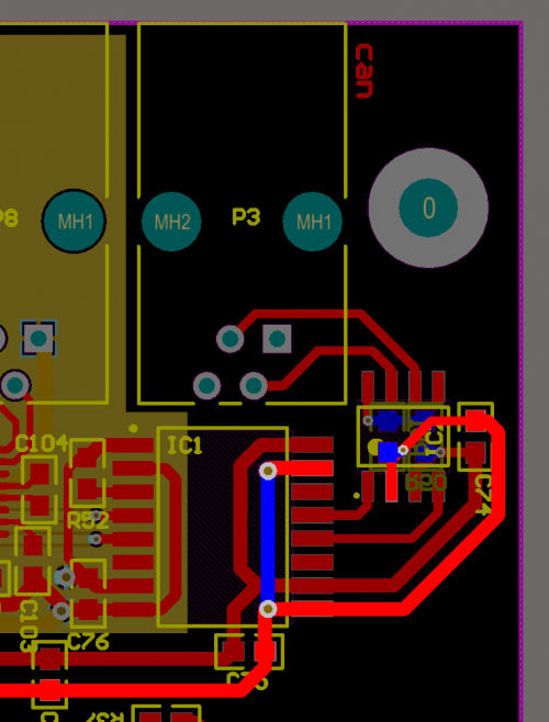
If CAN is used to connect to a drive with high power, CAN GND must be connected. This connection is missing on the board version 11 and 20. You have to connect GND_ISO with pin4 of the CAN connector. The highlighted lines are GND_ISO and CAN GND.


