Infoportal
Inhaltsverzeichnis
EtherCAT Teststand
To be able to check the Recommended Workflow steps 1-8, we have a test bench equipped with two ELMO drives, see hardware description below. As host-machine you either use a x86 based PC or a PLC system CX2020. The following manual can be used for both machines.
A test program is available in which the drives turn the two motors while position and velocity data are logged. The code can be found under https://gitlab.ost.ch/tech/inf/public/ethercat-teststand. You will find two applications:
- standalone
- using EEROS
Build the Image with Yocto
In order to run the test program, you first have to build the correct image. Follow this (Setting up the Build Environment) to build the environment but:
Clone the following additional layers into the directory yocto:
Note: At the time of writing the latest LTS release is dunfell. Check the poky repository for all available releases.
git clone git://git.openembedded.org/meta-openembedded -b dunfell
git clone https://gitlab.ost.ch/tech/inf/public/meta-ost
git clone https://gitlab.ost.ch/tech/inf/projects/yocto/meta-ost-ethercat
Add these new layers in yocto/build/conf/bblayers.conf, so the file looks like this afterwards:
# POKY_BBLAYERS_CONF_VERSION is increased each time build/conf/bblayers.conf
# changes incompatibly
POKY_BBLAYERS_CONF_VERSION = "2"

BBPATH = "${TOPDIR}"
BBFILES ?= ""

BBLAYERS ?= " \
<path to yocto directory>/yocto/poky/meta \
<path to yocto directory>/yocto/poky/meta-poky \
<path to yocto directory>/yocto/poky/meta-yocto-bsp \
<path to yocto directory>/yocto/meta-openembedded/meta-oe \
<path to yocto directory> /yocto/meta-ost/meta-ost \
<path to yocto directory> /yocto/meta-ost-ethercat \
"
Make sure your yocto/build/conf/local.conf has the following settings:
…
MACHINE = "c6930"
…
DISTRO = "ost-distro"
…
CONF_VERSION = "1"
OST_DEVBUILD = "1"
CORE_IMAGE_EXTRA_INSTALL_append = " iproute2 canutils"
Choose the Right Machine
Since the linklayer configuration depends on the host machine, it must be chosen accordingly.
If you are using a PC as host, you can skip the following sentences and use the MACHINE = „c6930“ configuration and connect the ethernet port of the PC to the first elmo drive.
To connect the PLC with the Elmo-Drives via EtherCAT there are two possibilities. Either via the plug at the front of the PLC (X000/X001) or via a terminal module on the side of the PLC. Depending on this connection, the link layer must be set differently. To use the ports in front of the PLC, make sure your machine is MACHINE = „c6930“. To use the terminal modules on the side of the PLC use the MACHINE = „CX2020“ configuration.
The command to build the teststand-image is bitbake teststand-image but do not forget to source the build environment.
Flash the image
Follow this guide to flash the image to e.g. a USB-Stick.
The image was created in
<path to yocto directory>/build/tmp/deploy/images/c6930/teststand-image-c6930.wic.
Run the example
If the connection is not yet established, connect the PLC to the Elmo Drives via the port selected earlier.
Before running the example one has to unbind the ethernet port. Therefore you first have to find the PCI device. Either you query the Instance-ID via lspci commmand or simply run the program (as shown in the next steps) to get the Instance-ID from the thrown error message. With the now known Instance-ID, the driver name can be found with lspci -v.
Note: If you are using the test bench at OST Campus Buchs with the PLC CX2020 plug the ethernet connecter at port X000. This should be the port with Instance-ID 0000:03:00.0 and driver name e1000e.
Use this port, because the other port X001 can be used to access via ssh.
To now unbind the standard driver and load the EC LinkLayer module you can run the following three lines:
modprobe atemsys

echo '<Instance-ID>' > /sys/bus/pci/drivers/<driver-name>/unbind
# for example
echo '0000:03:00.0' > /sys/bus/pci/drivers/e1000e/unbind

modprobe atemsys
Now you are ready to run the test program.
Either the standard test program:
teststand -f /etc/eni/teststand.xml –i8254x 2 1 -dcmmode off -perf
or the test program with EEROS:
teststand_eeros -f /etc/eni/teststand.xml –i8254x 2 1 -dcmmode off -perf
Syntax:
- -f Path to corresponding ENI file 1)
- -i8254x Use LinkLayer „emllI8254x Intel Pro/1000“ for „Intel Pro/1000 network adapter cards“ if you use the plug in front of the PLC. If used via a terminal module on the side of the PLC use the Beckhoff link layer
-ccat. But you may also have a different link layer.- 2 <instance> Select the EtherCAT port.
- 1 <mode>
- Mode 0 = Interrupt mode (Interrupt mode is not supported for ECMasterDemo)
- Mode 1 = Polling mode
- -dcmmode on = enable dcmmode, off = disable dcmmode
- -perf Display performance measurements (Enable max. and average time measurement in μs for all EtherCAT jobs)
Findings
- When ENI are not setup correctly, the process data image can show strange alignment problems.
- Velocity readings on the teststand may vary greatly. The internal sampling rate of the drive may be 8 times higher than the sampling on the bus with 1ms. This leads to very few ticks, because the encoder has 25000 ticks per turn and the velocity is very slow. The drive obviously has an internal filter / observer .
- There is a emergency stop button. This button is connected to a digital input of the ELMO drive. However, we currently do not read this input, because that's not possible with PDO transfers.
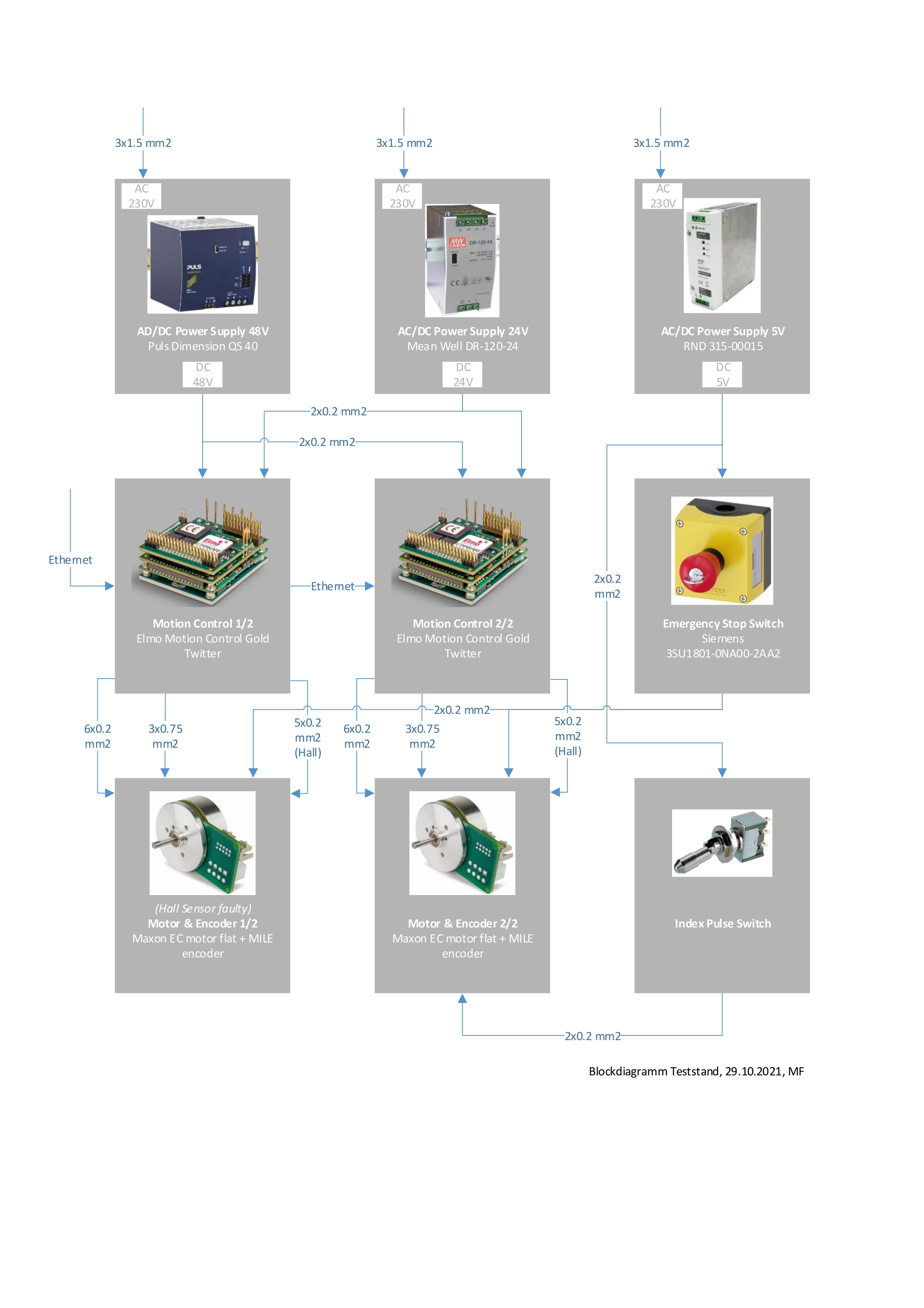
Hardware
The drives are Gold Twitter drives from ElmoMC. All datasheets and the standalone test-program code inclusive corresponding ENI-file are stored in the following GitLab repository: ethercat-teststand Repository.
1)
The ENI file is already provided in the cloned repository. If you want to change the EtherCAT network, create a new ENI file as described in Create an ENI File.