Infoportal
Understanding Synchronisation with Distributed Clocks
Additional Documentation
- Beckhoff documentation (Very extensive)
The Sync0 Synchronisation Signal
In a DC system each participant has its own clock which is synchronized with all other clocks. The Sync0 event is triggered synchronously on all participants.
The Sync0 Event
The Sync0 event ist triggered on all devices of the network at the same time. The slaves can read inputs and set outputs after a deterministic and configurable time (1C32:06 + 1C32:09) after the Sync0 event. Thus it is possible that all outputs in the whole network are set simultaneously within nanoseconds. The same is true for reading inputs at a determenistic time. It is also possible to set the outputs with a desired time delay.

DCM Master Shift Mode
In „DCM Master Shift Mode“ the hardware clock of the first slave is used as main clock. All slave clocks as well as the master clock are synchronized with this clock.
The jitter of the master has no direct influence on the jitter of the Sync0 event. However, if the jitter of the master is too high and the period too short, an EC frame may be sent too late. The slaves then do not receive the data sufficiently early before the next Sync0 even is triggeredt.
The coresponding error message will be something like:
082039 : eUsrJob_ProcessAllRxFrames - not all previously sent frames are received/processed (frame loss)!
DCM Bus Shift Mode
In „DCM Bus Shift Mode“ the clock of the master is used as the main clock. All slaves are synchronized with the clock of the master. The jitter of the master directly influences the jitter of the Sync0 event.
Master
After the Sync0 event, the received data from the Ethernet driver are first copied into the buffer of the Acontis stack on the master. Then the application can evaluate the received data and set the outputs. As soon as the cyclic job of the application is completed, the EC Frame is sent from the master to the slaves.
Cycle time
The cycle time between the EtherCAT frames is only deterministic to a limited extent. If the application needs in one cycle more time to calculate the results, the frames are sent later than in the cycle before.
The time between two consecutive inputs measurements is very constant, because they are synchronized with the Sync0 event. The same is true for writing outputs.
For calculations in control applications, the period duration (setpoint!) must be used, not the measured time between two EtherCAT frames.
Example Setting and Read with a ELMO EtherCAT Slave
1000usec cycle
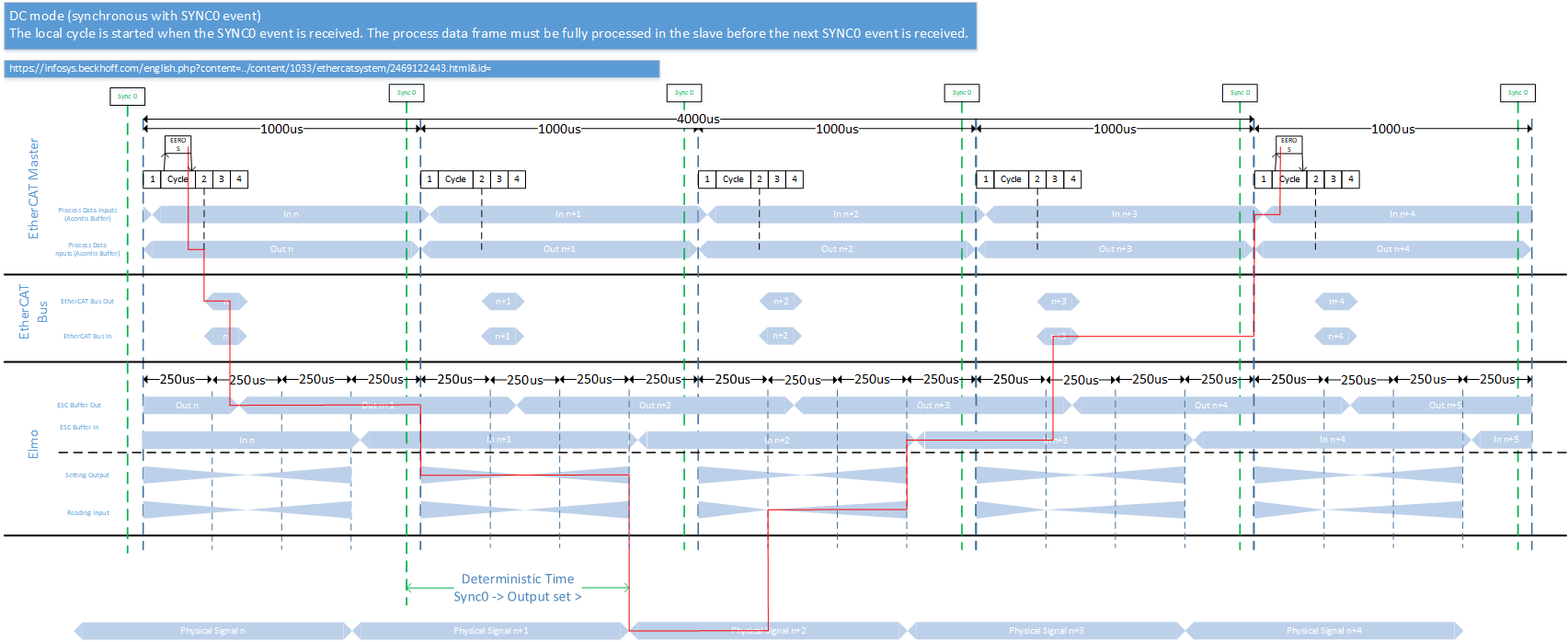
This example shows the flow of a signal through an EtherCAT network with an elmo Gold Twitter and a cycletime of 1000usec.
- The application sets a signal (e.g. a torque signal) which is forwarded from the Acontis stack to the EC bus.
- The stack sends the EC frame after the application is finished.
- The value is buffered in the ESC (EtherCAT Slave Controller) memory of the Elmo drive as soon as the EtherCAT frame is received from the Slave.
- With an Elmo Drive it takes up to 750 us until the physical output is set and valid after the Sync0 signal.
- Approx. 250 us after the next Sync0 signal the physical signal is captured again.
- After another 500 us, the value is buffered in the ESC's buffer memory.
- With the next EtherCAT frame the value is sent to the master.
- After the next Sync0 event the application can evaluate the signal.
250usec cycle
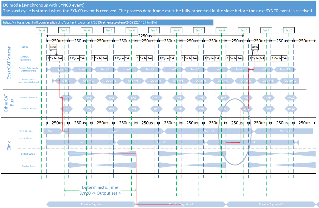 This example shows the flow of a signal through an EtherCAT network with an elmo Gold Twitter and a cycletime of 250usec.
Most of the lag is due to slow copy and write operations of the Gold Twitter controller. Another motor controller may be faster.
The delay marked with the circle may be omitted. Depending on the timing of the EtherCAT frame the data will be sent in the same cycle.
Notes to bandwith
The bandwith of EtherCAT is 100MBit/sec. If a large part of the bandwidth is used, then the transmission of the EtherCAT frame takes almost the entire period. This can lead to an additional latency of one period.