Infoportal
Dies ist eine alte Version des Dokuments!
Understanding Synchronisation with Distributed Clocks
The Sync0 Synchronisation Signal
In a DC system each participant has its own clock which is synchronized with all other clocks. The Sync0 event is triggered synchronously by all participants.
Master
After the Sync0 event, the received data from the Ethernet driver are first copied into the buffer of the Acontis stack on the master. Then the application can evaluate the received data and set the outputs. As soon as the cyclic job of the application is completed, the EC Frame is sent from the stack.
The period between the frames is only deterministic to a limited extent. In this mode only the period between the Sync 0 events is deterministic!
Example Setting and Read with a ELMO EtherCAT Slave
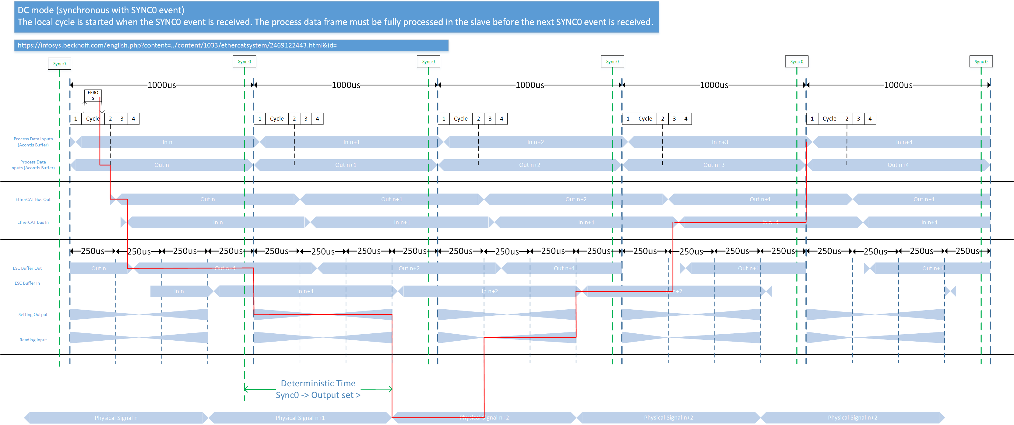
This example shows the flow of a signal through an EtherCAT network.
- The application sets a signal (e.g. a torque signal) which is forwarded from the Acontis stack to the EC bus.
- The stack sends the EC frame after the application is finished.
- The value is buffered in the ESC (EtherCAT Slave Controller) memory of the Elmo drive as soon as the EtherCAT frame is received from the Slave.
- With an Elmo Drive it takes up to 750 us until the physical output is set and valid after the Sync0 signal.
- Approx. 250 us after the next Sync0 signal the physical signal is captured again.
- After another 500 us, the value is buffered in the ESC's buffer memory.
- With the next EtherCAT frame the value is sent to the master.
- After the next Sync0 event the application can evaluate the signal.